Introducción

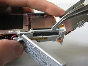
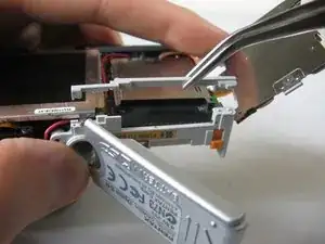
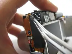
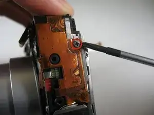
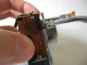
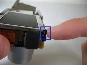
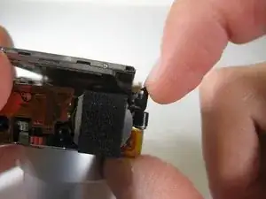
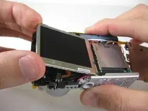
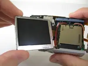
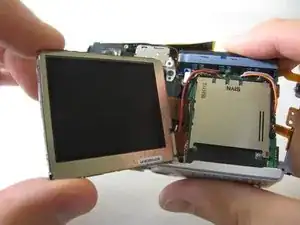
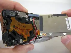
In this guide, you will be able to access and remove the LCD screen from the camera's frame.

  1. ZgmSVK6peCUBf5g4
    ZgmSVK6peCUBf5g4
    5DZJGlOkKtKhZxmg
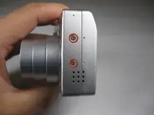
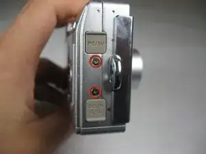
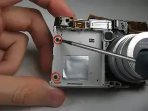
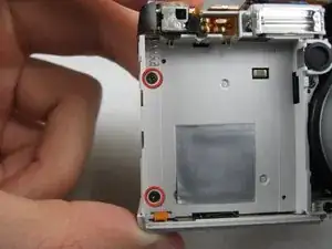
    • Remove the following screws:

    • Two silver 3.15mm Phillips #00 screws on the right side of the camera

    • Two silver 2.08mm Phillips #00 screws on the left side of the camera

  2. Ti2MvaIh4iSGDH3s
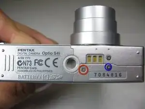
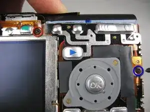
    • Remove the two indicated screws on the bottom of the camera:

    • The screw circled in red is a longer silver 3.15mm Phillips #00 screw

    • The screw circled in blue is a shorter silver 2.25mm Phillips #00 screw

  3. rKw34AmCEhmfFhgE
    rKw34AmCEhmfFhgE
    vDRrY3eqsohAgLjH
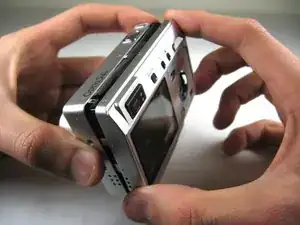
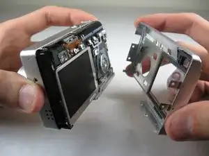
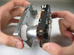
    • Carefully pull the back of casing away from the front.

  4. TGBSGe6PpZ11OVdL
    TGBSGe6PpZ11OVdL
    iOSWVovFCHRbIs6T
    ElILR2jSQVCxaeAx
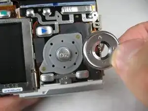
    • After removing the back cover, several things must be removed.

    • Silver donut-shaped button will fall off. Place separately. Remove the plug covers on the right side of camera, labeled “PC/AV” and “DC IN 4.5V”.

  5. MTriUeWyE6Up5xBj
    MTriUeWyE6Up5xBj
    2p3RoehZlahhOBFn
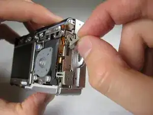
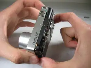
    • To remove the front cover, gently hold the inside structure of the camera and slowly pull the front cover off.

  6. RMroNjINRHArGyeI
    RMroNjINRHArGyeI
    lCdpX3WQGPxFAEiJ
    • On the front of the camera, in battery case, remove screws indicated:

    • Two black 2.05mm Phillips #00 screws

  7. WQOeJNaSbTwNcsDt
    WQOeJNaSbTwNcsDt
    Z1FQl4QA22ms32GZ
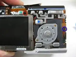
    • Flip the camera over to the backside and remove screws indicated:

    • The screw circled in red is a longer black 3.00mm Phillips #00 screw

    • The screw circled in red is a shorter black 2.00mm Phillips #00 screw

  8. GTiZx4gKo4myjeHB
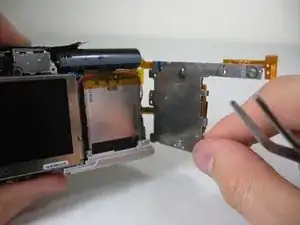
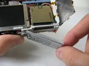
    • Pull the cover plate off for the two power cord jacks.

  9. HAxEQrFYaMGQBRgZ
    HAxEQrFYaMGQBRgZ
    AkIg3EuaNwvynN2A
    Gnrp1kFTbYihsVdX
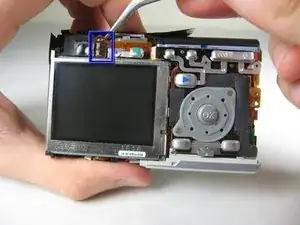
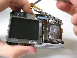
    • Cautiously and gently pull up the control board at the upper left corner, next to the viewfinder.

  10. SnV11aW5w55FiEDJ
    • Remove the orange tape on top of the SD cardholder.

  11. tQYoYYUP4SG1CUKS
    tQYoYYUP4SG1CUKS
    jAB3654L3YTkCplk
    Z3HZJOOJGNHXv33T
    • Open the battery cover and lift plastic piece off.

  12. k3ajIojyJmwvCQnG
    • Remove tape on left side of camera.

  13. lBS6iYeZ53dFK2Xv
    • Remove the indicated 2.40mm Phillips #00 screw to release top left LCD bracket.

  14. yr2FBrqVHNNyKbWG
    • Remove top left LCD bracket.

    • This is a small piece, be careful not to lose it.

  15. LuetwHUBYIKr4Oqf
    LuetwHUBYIKr4Oqf
    WdOP6FFQFrQJQIZE
    • Push down bottom left LCD bracket to release the LCD from grip.

  16. CTPiM2EAWwxYPAeR
    • Gently lift up LCD screen.

  17. CGfHtjEslnWBWHZg
    CGfHtjEslnWBWHZg
    LxVYlZGjVA3UehOI
    OZlHXXg4kcSbIiwy
    • Slowly pull LCD screen to the left to remove it from the other grips.

    • BEWARE: The LCD screen is attached to the logic board by two wires at the bottom.

Conclusión

To reassemble your device, follow these instructions in reverse order.

Bassem Tossoun

Miembro Desde 21/01/11

201 Reputación

0 comentarios